Animation of a Mechanical Rate Gyro
Introduction
The mechanical Rate Gyro was a staple of most inertial stabilization systems until a few decades ago. The inertial property that the Rate Gyro uses is angular momentum. Angular momentum is constant unless some outside torque causes the frame in which the spinning rotor is held to rotate. Then the rotor axis moves in the direction of the torque vector as shown in Figure 1.
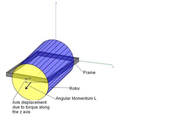
Figure 1: Diagram of the rate gyro showing the rotor,
the frame in which the rotor is housed, and the displacement of the front of
the rotor due to torque about the z axis.
The axle at the back end of the rotor is flexible so that the front end
of rotor can move up or down or left and right relative to the frame depending
on whether the torque on the frame is along the z or the y axis.
Mathematics
The angular momentum of the rotor shown in Figure 1 is nominally along the x axis. The relation between the angular momentum, L, and the torque, t, is
![]() (1)
(1)
Attempting to rotate the rate gyro frame about the z axis requires a torque which depends on the rate of rotation. For example, if we have the following variation of L:
![]() (2)
(2)
where W is the
radian rotation frequency and the equation describes the L vector making
circles about the z axis.
Then, according to equation 1, it would seem that the torque required to perform this rotation is:
![]() (3)
(3)
It’s obvious that the vector in equation 3 is perpendicular to that in equation 2 since the dot product of the 2 equations is:
![]() (4)
(4)
so that the dL/dt vectors follow the tip of the L vector around the circle that it makes.
But equation 3 results from the assumption that L and t are normal vectors. They are actually pseudo-vectors which have a handedness or chirality, so the equation for the torque in this case is the following cross-product:
![]() (5)
(5)
where L is in the x-y plane and W is along the z axis and
is the radian frequency of precession about the z axis.
However, another reaction of the rotor to the torque about the z axis is that the tip of the L vector must rise or fall out of the x-y plane by an amount proportional to the rate of rotation of the L vector by the angle Q:
![]() (6)
(6)
where k (n-m/radian)
is the bending spring constant of the flexible axle at the back of the rotor.
When the rate gyro frame is solidly mounted in a vehicle, and the vehicle makes a turn about the z axis of the frame, that requires a force that is perpendicular to the momentum, L, and in the (x,y) plane of the frame. In terms of force and distance, r, of that force from the axis of rotation, torque is given by:
![]()
If the distance at which this force is applied from the rotation axis is the vector r and r is along the momentum L, then the torque applied is
![]() (7)
(7)
where the vector F must be a function of time in order to remain perpendicular to L given by equation 2
![]() (8)
(8)
![]() (9)
(9)
where the values of r0 and Fo still
need to be evaluated.
Then the cross product given in equation 7 becomes:
![]() (10)
(10)
Equation 8 shows that the reaction torque to the force applied to rotate the L vector is along the –z direction and therefore there will be an incremental displacement of the L vector along the –z direction.
Now we need
to compute the direct values of r and Fo applied by the vehicle to
rotate the L vector in the (x,y) plane as specified by equation 2. The resulting variation in angular momentum
is given by equation 3
![]()
while r is given by equation 8.
![]()
Then we have the following equation for F(t):
![]()
Using equation 8 for r(t) we have:
![]() (11)
(11)
The only way that equation 11 can be satisfied is for F(t) to be perpendicular to both the y and x axes which means F(t) is along the z axis. We note that
![]() (12)
(12)
Using equations 12 in equation 11 we then have
![]() (13)
(13)
so that F is along the +z axis and is constant. Using equation 13 in equation 10 we get:
![]() (14)
(14)
Further, using equation 14 in equation 6 we get:
![]() (15)
(15)
Discussion
The foregoing math computes the deflection of the tip of the L vector when a rate gyro is mounted in a vehicle which rotates about the z axis shown in Figure 1. That deflection can be used as feedback to stabilize the vehicle.
What is interesting, is that the
force that the vehicle needs to apply in order to rotate the L vector in the
(x,y) plane is parallel to the z axis.
Therefore, if the z axis is the yaw axis of the vehicle and the rotor
axis is aligned with the roll axis of the vehicle, when the vehicle rotates
about its yaw axis, the force which needs to be applied to the vehicle due to
the inertia of the rotor tends to make the vehicle rotate in its pitch axis. With a really large rotor that could have
extreme consequences. For example, the
rotor could be a turbine or propeller and engine that is aligned with the roll
axis of the vehicle.